
Standard Operating Procedures Covering Hardware Faults, Parameter Settings, and Deep Wake-Up
Lithium Iron Phosphate ($\text{LiFePO}_4$) batteries are renowned for their exceptional lifespan, thermal stability, and deep cycling capabilities. A standard 48V 50Ah $\text{LiFePO}_4$ battery pack (typically configured in a $16\text{S}$ arrangement using 3.2V nominal cells) is widely deployed in telecommunications, solar energy storage, and light electric vehicles. However, when such a pack fails to hold a charge, it disrupts critical operations.
Diagnosing and resolving this issue requires a systematic, data-driven approach, examining everything from external charging parameters to internal cell balance and Battery Management System (BMS) integrity.
1. Initial Diagnostic Framework & External Factors
Before dismantling the battery pack or suspecting permanent cell degradation, technicians must rule out environmental and peripheral equipment failures.
-
Ambient Temperature Restrictions: $\text{LiFePO}_4$ chemistry possesses strict thermal boundaries. Charging below $0^\circ\text{C}$ ($32^\circ\text{F}$) without low-temperature cutoff protection triggers lithium plating on the anode, causing irreversible capacity loss and internal short circuits.
-
Charger Output Verification: A mismatch between the charger’s output profile and the battery requirements will prevent proper charging. A 16-series 48V $\text{LiFePO}_4$ battery requires a bulk/absorption voltage typically between 56.8V and 58.4V (3.55V to 3.65V per cell). If a standard 48V lead-acid charger is used, its float voltage is too low, and its desulfurization mode may trigger BMS fault protections.
Diagnostic Parameter Benchmarks
| Parameter | Normal Operating Range | Fault Threshold / Warning Sign |
| Charger Output Voltage | $56.8\text{V} – 58.4\text{V}$ | $< 54.0\text{V}$ (Under-voltage output) |
| BMS Cutoff Voltage (Over-Charge) | $3.65\text{V} – 3.80\text{V}$ per cell | $> 3.90\text{V}$ (Cell runaway risk) |
| BMS Cutoff Voltage (Under-Discharge) | $2.50\text{V} – 2.80\text{V}$ per cell | $< 2.00\text{V}$ (Deep sleep / Lockout) |
| Operating Temperature (Charge) | $0^\circ\text{C}$ to $45^\circ\text{C}$ | $< 0^\circ\text{C}$ (Plating risk) |
| Internal Resistance (Healthy Pack) | $< 30\,\text{m}\Omega$ (Total pack) | $> 80\,\text{m}\Omega$ (Degraded / High resistance) |
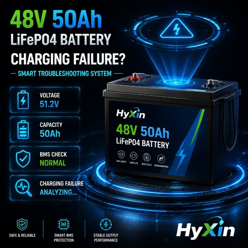

2. BMS Protection and “Sleep Mode” Recovery
The Battery Management System is the brain of the 48V 50Ah pack, designed to disconnect the circuit during over-voltage, under-voltage, over-current, or short-circuit events.
-
Under-Voltage Lockout: If a 48V pack discharges below its absolute minimum threshold (typically around $40\text{V}$ to $44\text{V}$, or $2.5\text{V}$ per cell), the BMS enters a protection shutdown state and cuts off the discharge/charge MOSFETs. In this state, standard smart chargers may read “0V” at the terminals and refuse to initiate a charge cycle because they detect no opposing voltage.
-
Recovery Procedure: To wake a sleeping BMS, technicians must apply a dedicated lithium charger with a “0V wake-up” or “forced charge” function, or connect a compatible power supply capable of delivering a controlled, low-current pre-charge until individual cell voltages rise above the $2.8\text{V}$ recovery threshold.
3. Internal Cell Imbalance and Capacity Degradation
If external variables and BMS settings are normal, the root cause usually lies within the internal $16\text{S}$ cell architecture.
The Weak-Link Phenomenon in Series Strings
A 48V 50Ah pack relies on the uniform capacity of 16 individual cells connected in series. If even a single cell degrades, exhibits higher internal resistance, or suffers from self-discharge, it reaches its full charge state ($\sim 3.65\text{V}$) or empty state ($\sim 2.5\text{V}$) long before the rest of the pack.
-
Premature Charging Cutoff: During charging, if Cell #7 reaches $3.65\text{V}$ prematurely due to capacity fade (e.g., dropping from 50Ah to 35Ah), the BMS immediately shuts down charging to protect that specific cell. Consequently, the overall 48V pack remains only partially charged, manifesting as a failure to hold energy.
-
Cell Balancing Limitations: Standard BMS balancing currents are relatively small (usually $30\text{mA}$ to $100\text{mA}$). If the delta voltage between cells exceeds $100\text{mV}$, passive balancing cannot correct the drift during a standard charging window, requiring manual top-balancing.
4. Step-by-Step Troubleshooting Protocol
-
Step 1: Terminal Voltage Measurement
Measure the open-circuit voltage (OCV) across the main positive and negative terminals using a calibrated digital multimeter.
-
Reading is $48\text{V} – 54\text{V}$: Pack is operational; proceed to capacity testing.
-
Reading is $0\text{V}$: BMS has tripped via protection mode or internal fuse is blown.
-
-
Step 2: Check Fuse and Continuity
Inspect the internal or external main fuse. High current spikes can blow the master fuse, isolating the cells from the external terminals while the internal cells remain intact.
-
Step 3: Access and Measure Individual Cell Voltages
Carefully open the protective casing (observing anti-static and insulated tool protocols) to access the BMS balancing harness. Measure the voltage of each of the 16 individual cells.
-
Healthy Delta: Cell voltage variance should be $< 30\text{mV}$ at full charge.
-
Faulty Delta: Variance $> 200\text{mV}$ indicates severe cell imbalance or capacity degradation.
-
-
Step 4: Perform Manual Top-Balancing
If imbalance is confirmed, disconnect the BMS and charge individual low-voltage cells using a single-cell 3.65V bench power supply until all cells match precisely, then reset the BMS cycle.
Conclusion
Troubleshooting and repairing a 48V 50Ah LiFePO4 battery that fails to hold a charge relies on a step-by-step, inside-out approach. Starting with ruling out external ambient temperature limits and charger output compatibility, moving on to identifying BMS low-voltage protection and “sleep” states, and finally diving into the voltage differential and capacity degradation analysis of the internal $16\text{S}$ series cells, every step requires precise data support. Through standardized multimeter measurements, fuse inspections, individual cell delta diagnostics, and necessary manual top-balancing procedures, technicians can efficiently pinpoint the root cause, maximize the restoration of the battery pack’s energy storage performance and service lifespan, and ensure the safe and reliable operation of the energy storage system.
Please contact us for more information!
Related LiFePO4 Battery Engineering Guides & Factory Models
For B2B procurement, UN38.3 MSDS compliance, and Grade-A prismatic cell matching, review these related HYXin technical resources and production models:
- Grade-A LiFePO4 Cell & Pack Specification: 200Ah 25.6V Reliable LiFePO4 Battery Packs BMS Protection w/ BT for Household battery system
- Technical Engineering Guide: 48V Battery Solutions for Autonomous Robots: Powering the Next Generation of AMR and AGV
- Technical Engineering Guide: How to assemble 16x LF160 cells into a 48V 160Ah telecom backup system?
- Technical Engineering Guide: Enhanced Market Drivers: 5G Powers the Next Stage of AGV/AMR Development
- Technical Engineering Guide: What is LiFePO4 Battery?
- Grade-A LiFePO4 Cell & Pack Specification: LF280K LiFePO4 battery cells 3.2V 280Ah Grade A 6000+ cycles for EVs, Solar Systems Versatile Power
- Grade-A LiFePO4 Cell & Pack Specification: Topband 25Ah 3.2V RV Marine Rechargeable LiFePO4 Battery A Grade Brand New Long Lifespan Battery
- Technical Engineering Guide: Can a 48V 50Ah LiFePO4 Battery Be Used for a Motorcycle? In-Depth Analysis and Conversion Guide
- Technical Engineering Guide: Lifespan of 300Ah Cells at 100% DoD in Heavy-Duty Forklifts
- Technical Engineering Guide: What is REPT 50Ah LiFepo4 Battery
- Technical Engineering Guide: EVE 3.2v 280Ah LiFePO4 Battery Export to Ukraine
- Technical Engineering Guide: How to Effectively Utilize the Energy Management Features of Integrated LiFePO4 Systems?